Hi Dor,
I don't follow all your email but in general you can add the
powers (magnitudes squared) of the FFT bins to give you the
equivalent of power in the time domain (Parceval's theorem).
Strictly speaking I recall there is a slight tweak to the DC bin
value but I don't remember the detail. It goes without saying
that baseband signals and FFT bin values are complex (IQ).
Keep in mind that when you feed a single frequency into an FFT, it may fall between 2 bins. In this case the peak will be lowered (scalloping loss). You might want to consider the use of a suitable window to compensate for this. The window will lower the total power, which you also need to allow for.
I think -15 dBm is the point beyond which saturation,
distortion or worse might occur. The point at which you reach
full scale on the ADC will depend on the front end gain setting.
I don't know what this might be for your set up. At some gain
settings compression might occur in the analogue front end
before you reach full scale. Gain will also be frequency and
temperature dependent to some degree. The UBX-160 datasheet
lacks detail.
I have experience calibrating the X310 but with a different
front end, using GNU radio to capture the baseband signal but
Matlab to process it.
Regards,
Steve
Hello,
I wish to use USRPX310 with UBX-160 daughterboard as a calibrated spectrum analyzer to show the received signal power in units of [dBm] and [dBFS] for my setup.
I've read discussion and the GNURadio FAQ before so I know I must calibrate my setup because the values in GNURadio don't mean a thing.
So I wanted to ask if this procedure seems to make sense for you. I will be glad to receive any suggestions.
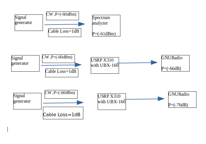
I'm gonna connect my signal generator to spectrum analyzer to measure the cable loss.After that, gonna connect it to the USRP to measure the power[dB] in order to understand what is the power[dBm] in GNURadio.
Is this table correct to calibrate and calculate the Power[dBm] on GNURadio in FFT?
Signal generator Power[dBm] Power [dBm] on spectrum anlayzer Power[dB] on GNURadio in FFT Power[dBm] on GNURadio in FFT -60 -61 -66 -61 -65 -66 -71 -66 -70 -71 -76 -71 -75 -76 -81 -76 -80 -81 -86 -81 -85 -86 -91 -86 -90 -91 -96 -91
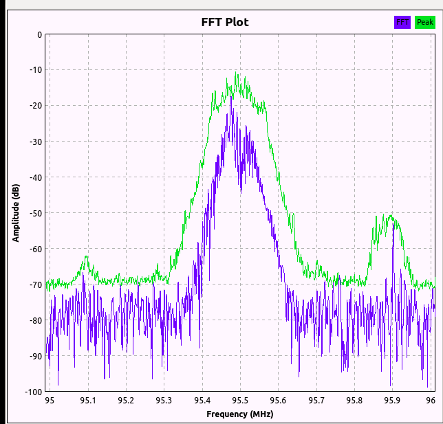
Procedure for wideband signal (not CW)Right now the power[dB] must be calculated with the occupied FFT bins, let's assume this is the signal and the NFFT=128, so we can see that the signal occupies only 2/10 grids in the FFT so:
Power_of_signal[dB] = Peak_power[dB]+ 10*log(FFT_bins_with_signal) = (-15dB) + 10*log10((2/10)*(128)) = (-15dB) + (14) = (-1dB)
Convert to dBFS for the USRP X310
How do you propose to do it?
The ADC of X310 has 14 bits. so the MSB values are 2^13 = + - 8192 (signed values).
Power[dBFS] = 20*log10(voltage_value_measured/8192)
Some questions:
- Does the gnuradio amplitude axis in QT GUI TIME DOMAIN are always float-point values in the range {-1.0,+1.0} for a received signal from USRP?
- If the answer to 1 is yes, then if I see amplitude = 0.5 , does it mean 20*log10(0.5)=(-6dBFS) ? is that correct?
- I know that the maximum input power for the UBX is (-15 dBm), but what does it mean that (-15dBm) input power is 0[dBFS]?
- Has anyone had experience with RX power calibration of USRPX310 with UBX-160?
If I understand correctly, it is supporting the power API:
ThanksDor